Because my room is facing the rest of the U-shaped block of the apartment, it is rather easy to look into from outside at night time, even without a pair of binoculars. Changing clothes in my room would thus require you to switch off the lights or draw the curtains. However, doing so would mean you can't see the clothes you are choosing, and that would mean you have to switch on the light to choose, switch it off to change, then switch it on again to see whether you look ok, before either: switching off when you leave the room, or choosing another piece of clothing and switching off to try, and then switch on to... you get my point. All this switching off and on can be a hassle, and is bad for the bulb anyway. This is why I chose to make this cupboard light. And while I am at it, might as well make it more convenient and energy saving. I will make it such that it only turns on when my room is dim. If I have my room light on, I can see my clothing in my cupboard perfectly well, and so do not need the light to turn on. So it has to have a light sensor along with a contact switch.
Firstly, conceptually it might be simple, and it is, but you don't want to just hook up the circuit to a simple transistor, because then your on and off will be rather gradual. For example, as ambient light dies, your lighting circuit will gradually become brighter, rather than having a sharp transition as though someone flicked a switch. This will cause problems in certain light where ambient light is not bright enough, and your lighting circuit hasn't fully come on, so you're still in a very dim environment. Placing an op-amp in a "comparator" configuration, instead of just a single transistor circuit, solves the problem.
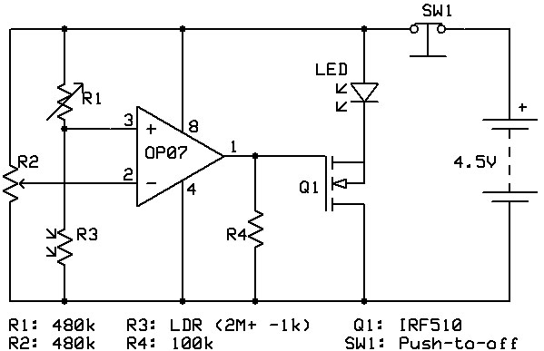
Above is the circuit schematic. You don't really need to know much to construct this, but it'll help you because you will know how to troubleshoot or tune the device to your liking. This circuit has been constructed to use as little energy as possible when off, if not none, depending on the conditions. Here's how it works (in general): The switch is a contact switch placed such a way that when you close the door, the circuit breaks and the entire circuit is open (no electrical consumption at all). It's much like the fridge. And when your door is open, the circuit will be on, but will take information from the light sensor to determine if the light should be switched on or not. If the signal is no, and the light remains off, the circuit consumes very little power as well. I will not explain the details of this circuit. If you're interested to find out how it really works, look up: LDR (Light dependent Resistor), Op-Amp (operational amplifier) in comparator configuration, voltage divider (principle), and the transistor.
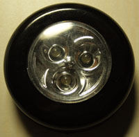
I didn't want to construct the light, so I just went to buy myself a cheap one. It's one of those press-on lights that run on 3 AAAs. LEDs take up very little power and can be quite bright too, which is great for a lighting circuit that's going to run on batteries. No point getting an AC adaptor that you have to keep on all the time. AC adaptors when plugged in and switched on, even without any device attached to it (or the attached device is off) consumes quite a fair bit of power that's significant to your electricity bill. Don't forget the environment too!
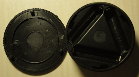
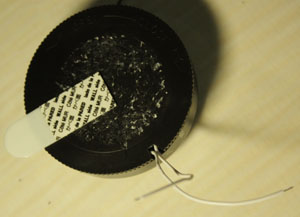
So dismantling it, I see the battery holder arrangement is in a triangle. A bit of closer inspection reveals that they are all connected in series, with only 2 points running to the LEDs. This means, all I have to do is really to supply power to two contacts and the LEDs will light up.
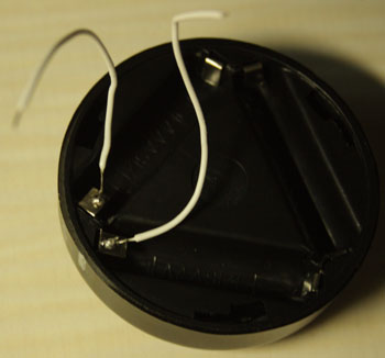
So, I solder two wires to these points. I also tested them with an external battery holder to check if all went well. Sometimes, while soldering, solder inside the casing might melt and cause internal disconnections, so the rule is to always solder as fast as you can, and do tests whenever possible to reduce the problems and complications when troubleshooting after the entire circuit is put together.
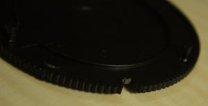
Now that I have the wires sticking out from there, the backcover will not fit over the LED light anymore. A notch must be made to let the wires out.
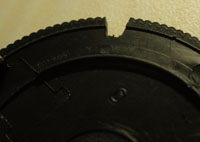
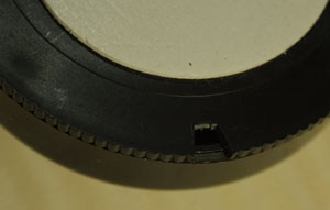
Now putting the cover on is possible. I took away the adhesive that comes with the cover because I prefer to use 3M's Command Strips which can be easily removed without taking off paint from your walls, or leaving ugly markings on your wood (which my cupboard is made of)
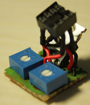
Just construct the circuit in the smallest possible form. I tried to squeeze all the components into as small a board as I could, to take up less space, but it still looks rather ugly. Note that I did not put the op-amp in yet. What you see is just the holder.
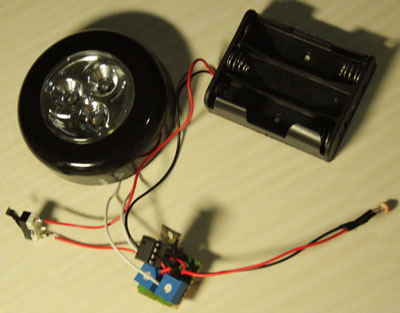
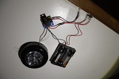
Just solder everything together, and the setup is ready for mounting. Going clockwise from the top left of this picture is the LED lights, the 3 AA battery holder (lasts longer than AAAs), the LDR (light dependent resistor), the circuitry, and the contact switch.
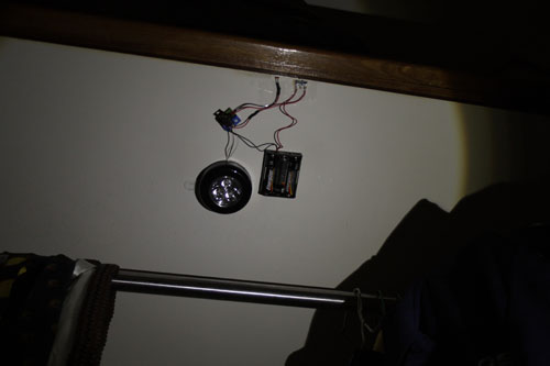
I mounted it to the ceiling of my cupboard, and adjusted the variable resistors to tune it to my liking. I don't expect to change the batteries for at least a year, since this is a low consumption circuit, and specifically designed as so. Hope the batteries don't leak on me.